Camera Intervalometer
Compatible with LRTimelapse Pro‑Timer Free
August, 2017
A friend asked me to build him two LRTimlapse Pro‑Timer Free intervalometers, using Gunther Wegner's designs and instructions. My thought process for what I ended up with was as follows:
-
I don't want to have to source the 3D printed case. I'm experienced with drilling and cutting enclosures for electronic projects, so I'll use an "off the shelf" blank case. I'm also experienced with designing and building electronic devices, so any additional wiring isn't a problem.
-
This presents the problem of how to make the buttons on the SainSmart LCD display shield easily accessible from outside the case. The original does this with button extenders but that could be tricky to engineer myself.
-
Also, my friend asked that it be at least splash and dust resistant, if possible. With the original, water, dust, etc. can enter through the gaps between the case and the button extenders (and even more so through the display opening).
-
It will be easier to use buttons that can be panel mounted in drilled holes. I can then use buttons that meet the "splash proof" requirement. This also allows the buttons to be bigger and spread out for easier operation. (My friend said making the unit somewhat larger than the original is acceptable.)
-
So now the buttons on the display shield aren't being used. The shield uses a common LCD display module and only a handful of other standard, easily obtainable components. I may as well buy the LCD module and wire it to the other required components on my own board. Since I'm only building two, I won't go to the trouble of laying out and having a printed circuit board made. I'll just hand wire everything on perfboard.
-
I'm making my own display board, and wiring the buttons separately, so I'm no longer restricted to my board being an Arduino shield. It can be any size or shape. This means I don't have to use an Arduino board capable of accepting a shield. I'll use the Arduino Pro Mini. It has the required compatibility with the Arduino UNO used in the original but it's smaller and generally less expensive.
-
Unlike the UNO, the Pro Mini is available in a 3.3V 8MHz version, in addition to the 5V 16MHz version. I've looked at the source code and determined that the software should work correctly at 8MHz without changes. Versions of the display module are available that run at 3.3V and no other aspect of the hardware prevents operating at 3.3V. This will allow using 3 batteries in series instead of the original 4. And, using the Pro Mini's on board 3.3V regulator, which accepts inputs from 3.4V to 12V, both rechargeable and non-rechargeable batteries can be used, instead of the original's "rechargeables only" requirement. The Pro Mini's regulator is more than capable of providing the power required for itself, the display and the rest of the circuitry.
-
The Arduino Pro Mini is small enough that it can go on the perfboard along with the other components. The board can be made a similar size to the display module and the two can be sandwiched together and connected by socket and pin headers, much like the shield is attached to the UNO in the original. Since there will only be one row of 12 pins, this won't be enough to physically hold the board and display together. I'll use threaded standoffs to join the two.
-
With the Arduino running at 3.3V/8MHz, it will use much less power than running at 5V/16MHz. Also, I won't include the power indicator LED that's on the SainSmart shield and I can disable the Pro Mini's power indicator LED, since neither will be visible from outside the case. Because of the lower power, I can use AAA size cells instead of AA size cells, to save size and weight, and still have a long battery life.
(I measured the current draw of the finished units. It's about 5.5mA with the display backlight off and about 7.1mA with backlight on, which should give a few days of run time with AAA NiMH rechargeables even with the backlight on, and probably over a week with disposable alkalines and the backlight off.)
TL;DR Summary
-
The Arduino UNO and SainSmart shield used in the original will be replaced by a perfboard holding an Arduino Pro Mini and support components, connected to the same type of LCD display module (but a 3.3V version) used by the SainSmart shield.
-
Larger buttons will be used and mounted to the case.
-
The unit will run at 3.3V/8MHz instead of 5V/16MHz.
-
Power will come from 3 AAA cells of any type instead of 4 rechargeable NiMH AA cells.
-
The unit will be able to run the LRTimelapse Pro‑Timer Free software without requiring any code modifications.
Additional Enhancements
My design has a few modifications and additions:
-
There are separate transistors for the focus and trigger signals. A small slide switch on the board selects whether both signals are controlled by Arduino Pin 12 (for software compatibility), or trigger is controlled by Arduino Pin 12 and focus is controlled by Arduino Pin 11. Whether separate control will be useful for anything is unknown but it can't hurt, just in case.
Another purpose is so that trigger and focus aren't shorted together when inactive, for the (perhaps unlikely) case where having them always shorted causes problems for some camera(s).
-
The LCD contrast will start to fade soon after the batteries reach a voltage that's too low for the regulator to maintain 3.3V. With NiMH cells the unit will still operate for quite a while after the display starts to fade. However, with alkaline or other cells that have a higher voltage discharge curve that's steep at the end, there may not be much operating time left after display fading begins.
To address this, an added resistor divider across the batteries is fed to the Arduino analog input 1. This allows accurate measurement of the battery voltage. A potentiometer is included in the divider to allow the ratio to be adjusted for 200 counts per volt. Modified software can read the battery voltage and provide a better indication of the remaining life.
-
A "black on yellow" LCD display is used instead of the original "white on blue" one. This transflective display is readable without the backlight down to fairly low ambient light conditions. At a light level where it's necessary to use it, the backlight was quite bright. An external dropping resistor has been added in series with the backlight circuit to reduce the backlight intensity. This also significantly reduces the current drawn by the backlight when it's on, from the original 24mA to 1.35mA.
-
As was mentioned earlier, the power indicator LED on the Arduino board can't be seen with the case closed. To save power, this LED has been disabled by cutting a trace on the Arduino board between the LED and its dropping resistor. The LED would draw 1.4mA when on.
Click on each photo to see a larger view.
Two boxes were built, so if parts or wires appear to have moved or changed slightly between photos it's likely that each photo is of a different unit.
Finished Unit
The aluminium case is a Hammond model 1590BB. Dimensions of the case itself are 119 x 94 x 34 millimetres (4.7 x 3.7 x 1.3 inches).
The push buttons are a common type that mount in a 7mm diameter hole. They are frequently called type PBS-110.
The power switch is a standard 14mm x 20mm snap-in panel mount rocker switch. This size is commonly found on desktop PC power supplies.
The 2.5mm TRS jack is a snap-in isolated type, so that none of the pins are in contact with the metal case.
The display cover window is made from 2mm thick clear acrylic.
Case
This is the empty case after machining for mounting the components.
The hole on the side for the 2.5mm jack is drilled then filed to the exact required size and shape so that the jack won't rotate if the plug is twisted while inserting or removing it.
Circuit Board
Through-hole components are used for ease of installing and wiring on the perfboard.
Machined round pin headers are used for the Arduino board to provide a lower overall height than square pin headers would. They also provide a more reliable contact.
The small slide switch selects common or separate control of the trigger and focus transistors.
The trimmer pot beside the switch is for adjusting the display contrast. The other trim pot adjusts the resistor divider ratio to calibrate the battery voltage monitor. Solid hook-up wire straps with Teflon tubing are used to anchor down the pots so they won't move while being adjusted.
The large hole between the Arduino socket strips is for accessing the reset button (though this may never be required).
A few supply decoupling capacitors have been added just because it's good design practice and can't hurt.
Arduino Pro Mini
The pin headers are installed on the top so that it mounts upside down on the perfboard, to give access to the reset button. This also reduces the overall height so the spacing between the perfboard and the display can be less. (Even so, extra long pins are required on the display because of the distance between the boards).
The programming header is mounted at an angle and has extra long pins to make it easy to attach the programmer. (A programmer is required because, unlike the UNO, the Pro Mini doesn't have on-board programming circuitry. An advantage of not having the programmer on-board is that it doesn't continuously waste power when not in use).
The Pro Mini used is a "clone" based on a design by Deek Robot. The board layout and circuitry isn't identical to an official Pro Mini but it functions the same from a software point of view.
To save power, the power indicator LED is disabled by cutting the trace between the LED and its dropping resistor, as indicated in the photo.
The Deek Robot design has a Schottky diode between the "raw" input and the voltage regulator, which the official Pro Mini doesn't have. The additional voltage drop across this diode causes the battery "cutoff voltage", where the regulator can no longer maintain 3.3V, to be higher. This reduces the overall run time from a set of batteries. The diode provides protection that isn't required in this situation, so it has been bypassed by adding a jumper to short it out, as indicated in the photo.
Pro Mini Mounted on Circuit Board
Wire straps are twisted and soldered to prevent the board from becoming unseated when the reset button is pushed or the programmer is inserted. Though probably not necessary, electrical tape is put on the board under the straps for insulation.
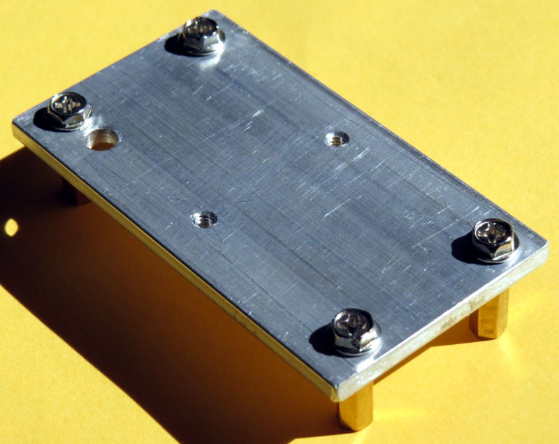
Mounting Plate for Battery Holder
To prevent having nuts or screw threads on the outside of the case, the battery holder is mounted on an aluminium plate. The plate is on M3 threaded brass standoffs, which brings the holder up higher in the case to make it easier to change the batteries. The holes for the holder screws are tapped with threads so that nuts aren't required. A large hole in one corner allows the wires to exit through the bottom of the holder and plate.
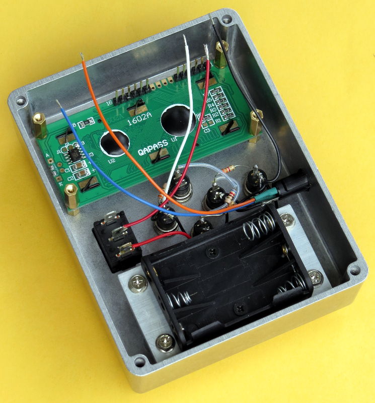
Components Installed and Wired
These photos show all components installed and wired except the perfboard.
All resistors for button sensing, except one on the perfboard, are wired directly to the buttons. Teflon tubing is put on some of the leads to prevent shorts.
The display is mounted with screws that each go through the acrylic window, the case, a short non-threaded brass standoff, the display board, then into a longer M3 threaded standoff. (The perfboard is held in with screws that go into the other end of the longer standoffs.)
Circuit Board Installed and Wired
Construction Complete
The wires from the other components are soldered to "flea clip" push-in terminals on the perfboard.
Back Cover
A 1/4-20 threaded insert is installed in the centre of the cover to provide a solid mounting point. The buttons are located and wired such that a screw in the insert can go as deep as the depth of the case without interference.
The black foam pad on the cover presses down on the batteries to hold them firmly in place.
Arduino Programmer
Any Arduino Pro Micro compatible serial programmer can be used but it must be capable of 3.3V operation.
Although the CH340G based programmer that was purchased has a switch for 5V or 3.3V operation, it turned out that the switch only affects the VCC output. All other outputs are always 5V when high (although through series 1K resistors, intended to provide a small amount of safety). The programmer was modified to provide proper 3.3V (only) operation. The modifications bypass the switch so it's position no longer has any effect.
The right angle male header originally on the top side of the programmer was replaced with a female header on the bottom, to properly mate with the pins on the perfboard.
THE END